

02 / 10
Data Centers
Server halls, white spaces, technical rooms, support areas and critical building infrastructure.
- Architectural
- Structural
- MEPF
- Coordination
Data halls stack cooling, power and cable containment into tight overhead and underfloor zones, and every route has to leave room for maintenance. The model resolves those layers row by row, so equipment can be installed and serviced as drawn.
What each discipline models
- L.01Architectural
Room layouts, partitions, doors and access zones.
- L.02Structural
Floor systems, equipment supports and framing.
- L.03MEPF
Cooling, ventilation, power distribution, cable containment, plumbing and fire protection.
- L.04Coordination
Dense overhead services, equipment clearances, maintenance access and routing interfaces.
Where these projects go wrong, and how the model prevents it
- C.01
Cooling, power and containment compete for the same overhead space
ApproachEach system is given a defined zone and level, then the zones are clash-tested together before any route is fixed.
- C.02
Equipment needs clear space to be installed and maintained
ApproachClearance and access volumes are modeled around equipment, so services that would block maintenance show up as clashes.
- C.03
Support framing has to suit heavy and dense equipment
ApproachFloor systems and equipment supports are modeled in the structural model and coordinated against the services they carry.
- Overhead cable containment stacked against cooling and ventilation
- Equipment clearances in white space and technical rooms
- Maintenance access to plant and distribution
- Routing interfaces between halls and support areas
- Architectural model of halls, technical rooms and access zones
- Structural model of floor systems and equipment supports
- Coordinated cooling, power, containment, plumbing and fire protection models
- Federated model with clash reports and a tracked issue log
Standard modeling capability: up to LOD 400, across every discipline.
LOD & Standards →Process
- 01
Brief & inputs
Drawings, models, standards and templates collected, with scope agreed by discipline and level of detail.
- 02
Discipline modeling
Each discipline modeled on the project's shared coordinate system, to your naming and template standards.
- 03
Federation & clash cycles
Models federated and clash-tested, with issues tracked through resolution with the responsible trades.
- 04
Sign-off & handover
Issue log closed out and coordinated models and drawings handed over, with a change log.
Data Centers: common questions
Yes. Cable tray and containment are part of the MEPF model and are coordinated against cooling, ventilation, plumbing and fire protection.
Same disciplines, different buildings
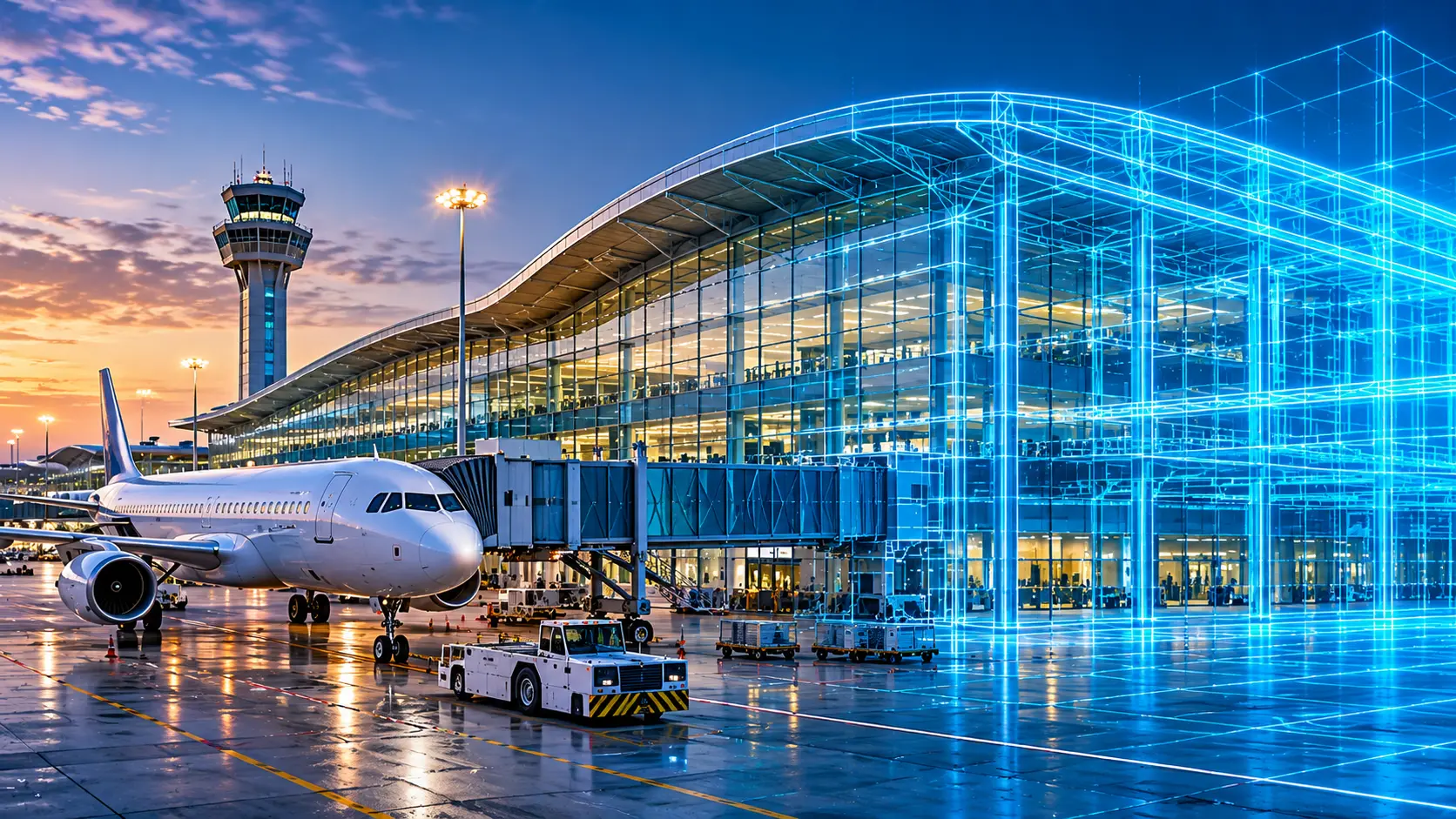 Illustrative render01
Airports & Transit
Terminal buildings, transit hubs and long-span structures, with MEPF coordinated through dense passenger areas.
- Architectural
- Structural
- MEPF
- Civil / Site
- Coordination
View Details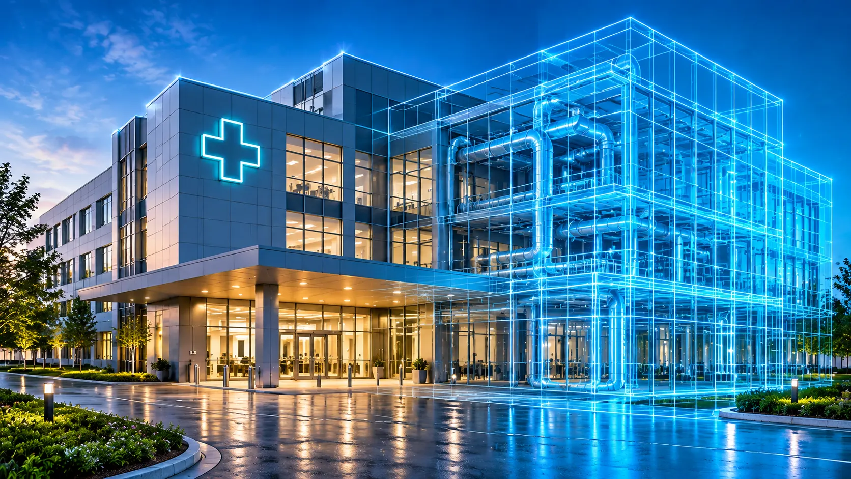 Illustrative render03
Healthcare
Hospitals, clinical spaces and complex building services, coordinated around access and clearance needs.
- Architectural
- Structural
- MEPF
- Coordination
View Details Illustrative render04
Industrial & Manufacturing
Industrial facilities, structural framing, piping and building services, coordinated for maintainable operations.
- Architectural
- Structural
- MEPF
- Civil / Site
- Coordination
View Details
STRATA models design intent supplied by your architect or engineer of record. We are not the architect or engineer of record on your project, and we do not stamp or seal drawings.
Ready to coordinate your next project?
Send your disciplines, LOD target, and project location. We come back with scope and next steps within 24 business hours.